Showing posts with label sparkfun. Show all posts

Monday, April 4, 2016

Vibration Robot - Iteration 1 - Chaos

I was always fascinated with the Kilobots developed by Harvard and their amazing capabilities when operated in massive swarms of self-organizing robots. I therefore decided to build my own prototype using modules easily available locally. This was not going to be a Kilobot clone but something different based on the same principle. So recently i managed to wrangle up a few breakout boards to make a vibration robot as shown below. The modules used are as follows

Main board - Arduino Lilypad (ATMega328) from Sparkfun. The reason i chose this was due to the large number of I/O and because the PCB is circular. 50 mm diameter, 17 mm more than that of the Kilobot, which is around 33mm.

Communications - Adafruit Bluetooh EZ Serial link. This board snugly fit on top of the Lilypads serial connector. The main board could now be programmed wirelessly over the BT Serial link.

Motor Driver - A Spakrfun TB6612FNG 1A Dual H-Bridge based motor driver for the vibration motors.

Power Source - A 400mAh Li-Ion battery similar to this. (External charger)


The orange colored housing for the motors is designed in my favorite CAD tool and 3D printed on me printer. The position of the holes  for mounting the screws was calculated from the board files supplied by Sparkfun. The motors were glued in their sockets. The entire assembly was held together using M3 screws through the Lilypad holes.


The block diagram of the system is shown below. The ATMega328 operates off the 3.7 V Li-Ion battery, which also powers the BT serial. The motor driver is powered from the 3.3V regulator on the BT serial board and draws maximum 2.2 mA of supply current, which is within spec of the regulator on the BT serial board as it can source maximum 100 mA. The driving voltage for the motors comes directly from the battery. Other control and PWM signals are connected to the arduino PWM and digital I/O pins.


And the end result after all that was - Chaos - as you can see in the video below. The robot is controlled via a windows phone application that i wrote which connected over BT serial to the bot. A single 4-Byte (integer) command was sent to the bot comprising of :

Byte 0 - PWM value for motor A (0 - 255)
Byte 1 - PWM value for motor B (0 - 255)
Byte 2 - Control signals for motors: Bit 1 - Motor A CCW, Bit 2 - Motor B CCW, Bit 3 - STANDBY/STOP
Byte 3 - Reserved.


The objective was to send varying PWM values to the motors to observe a linear motion along a straight line and characterize the 2DOF aspects of the system. Not shown in the video is my phone through which i am controlling the robot by varying the PWM to the motors.


Further iterations will include several improvements over shortcomings in the current design - thinner wires, smaller or custom boards etc. Thanks for watching...


Friday, August 29, 2014

Arduino + WizNet Ethernet Shield + Xively

I got this WizNet Ethernet Shield that i wanted to try out with the Arduino since the CC3000s proved to be a complete disaster. The shield appeared to be of chinese make and quiet different from the original Arduino Ethernet shield. I stacked my Sparkfun Weather shield on top of it as shown below only to find out that there was no provision to connect the I2C lines from the Arduino. SDA and SCL were not brought out onto the ethernet shield. Even the IOREF pin was not connected which was not helping the weather shield as the temperature and humidity sensor were interfaced using I2C and also needed the reference voltage. Looks like i have to tryout the original arduino ethernet shield sometime which has the I2C header present.Anyways i can only acquire the light sensor data using sparkfun shield using the existing setup.


 The code for the same is as below and what i had shown in an earlier post. The temperature and humidity settings have been zeroed out. The data is sent out to the Xively website.

Alternatively to test how effective the ethernet shield was i sent a value of 0 and 50 alternatively every 2 seconds to the Xively website. The code for that is shown below. Also shown below is the screenshot from the Xively site displaying the incoming data in the graph. Ideally the graph is supposed to be a continuous " saw waveform". The gaps that you can see are the connection to the xively site failing. It takes some amount of time to get back online. But it does recover unlike the CC3000 that goes into some infinite loop. So, apart from the fact that the I2C is messed up, i kinda like this shield. I hope the guys who made this shield add those I2C headers.... :)


Friday, July 4, 2014

Visible Light Communication Chronicles Part II


This is the continuation from Part I on my experiments with visible light communication that i posted sometime ago here. I set up a basic transmitter - receiver circuit, a square wave was given as an input to the transmitter and the output of the reciever was monitored. The transmitter consisted of a N-channel power MOSFET - P55NF06 driving a LED and the receiver consisted of the TEMT 6000 ambient light sensor. The square wave signal was generated using an Arduino MEGA and all the I/O signals were monitored using the Digilent Analog Discovery. Why i chose the above mentioned MOSFET ? because i already had it in stock and decided to use it. The light source is a commercially available 10 W high power LED which i got over here.

Transmitter

The overall circuit is shown below. The gate of the MOSFET is driven by one of the arduino pins. The sketch on the arduino is nothing but the blinky sketch. By adjusting the parameters to the delay function i could generate a square wave from 2 KHz (delay(1)) to 0.5 Hz (delay(1000). The gate resistors Rs and Rg were chosen such thar R1 << R2. From the datasheet, the P55NF06 N-channel mosfet has a drain-source voltage of 60V and a max drain current of 50A.The gate threshold voltage is around 2-4V. The LED forward voltage is around 7V. When turned ON the LED draws approximately 0.5 A which is within the spec of the MOSFET. The transmitter is assembled on a breadboard (yeah kind of not a good choice for a circuit like this, specially considering the mosfet parasitics, you never know...)


Receiver:

The receiver consists of the TEMT 6000 breakout board powered via a 3.3 V supply and it's output fed into the analog discovery. 

The distance between the RXR and TXR is 6 cm. I kept it small for initial measurements. All the signals seen on the scope of the analog discovery are shown below.


The above square wave has a time period of  2 seconds, 0.5 Hz. The blue signal is the input signal and the orange signal has been captured at the output of the ambient light sensor. Note that the rise time and fall time of both the signals appear to be instantaeneous. Also note that when the LED is OFF the TEMT sensor output does not drop to zero but goes to around 48 mV which as i mentioned in an earlier post is the interference from the fluorescent light in my room. The interference is visible in the above image when the input signal is 0V.


The input signal here is of 5 Hz. The output of the ambient light sensor follows the input given to the MOSFET. Note the ripple in the output when input goes to 0V.


In this case the input signal is of 50 Hz. Notice that the output signal starts exhibiting some non-linearity when the MOSFET turns OFF. The interference due to the fluorescent light starts getting negligible. More on this a scroll later.


In this case the input signal has a frequency of 500 Hz. If we continue to increase the frequency the signal at the output of the TEMT 6000 almost disappears and all we get is a DC voltage. with very faint signs of the input signal. After this initial test i decided to give the output of the UART to the TXR circuit and observe the output on the TEMT 6000. Here are the output response of the light sensor to different baud rates


300 Baud.


600 Baud. OFF time non-linearity starts kicking in.


2400 Baud.


4800 Baud. A still noticeable signal that can be recovered using some extra circuitry.


9600 Baud. Beyond 9600 you can only imagine what will happen to the signal at the sensor output.

To investigate on the TXR side. I used a 5V drain-source supply and switched the MOSFET using a 500 Hz gate signal. The following image shows the scope output. The output (orange) was taken at the drain hence the signal inversion. It can be seen that when the gate voltage drops to 0V, turning off the mosfet, the output voltage increases non-linearly with time.(based on the mosfet turn-off delay parameters). The delta is 46.7 usec. The datasheet says that the turn-off delay is around 30 nsec for the specified test conditions.


Allrighty that is a lot of information in this post. Part 3 of this series will elaborate on the analysis of the circuit, MOSFET parameters and the above plots.  Until then, take it easy...

Update

I did one more test in which i plotted the TEMT6000 output over the drain-source voltage Vds.


The orange plot is the output of the light sensor and the blue plot is Vds, which is inverted as i connected the scope to the drain as shown in the schematic. The nonlinearity that i had seen before was therefore confirmed to be due to the TEMTP 6000 sensor. I did a couple of tests with varying input frequencies and found that in all cases the time it took for the sensor outout to go from maximum to 0V was 1.4 msec.which means that it can handle signals from 1 Hz to 714 Hz approximately. This was true as seen in the output plots above. Increasing the Vcc for the sensor to 5V does not help. Time to find a better sendor or fix the output of this one. I will probably have to make a new board and change the 10K resistor to a more feasible value.


Wednesday, July 2, 2014

Visible Light Communication Chronicles Part I - The Light

I've begun experimenting with Visible Light Communication recently and hope to design a complete system using it. VLC is a promising means of communication having it's own bunch of pros and cons which i will not detail out here and waste my time and yours. Google It !! Nevertheless it is worth a try to design it and share the data with everyone on this planet.

I purchased a TEMT 6000 ambient light sensor breakout from Sparkfun as my first choice for a light sensor and check out it's performance. From the datasheet it can be seen that it has a fairly decent response in the visible light spectrum from around 400nm to 800 nm with peak sensitivity around 570 nm. I hooked it up to a 3.3V power supply and fed the ouput signal into my scope.


Now let me mention that my room has a flourescent light source - A tubelight. The light from this source is incident on the TEMT 6000 sensor. As i had expected the output on my scope is shown below. The signal was around 100 mV with an average frequency of 100 Hz. This was the "default" lighting of my room, call it the base lighting value. This is the output of the TEMT 6000. When i turned the light OFF and observed the output, the frequency component was not present, just a very small DC voltage resulting from the light from my laptop display.


When i superimposed light from an LED source directly on the sensor the effect of the flourescent light became negligible. The LED that i am using is this one. It is very bright, runs on 12V and draws around 2A of current. My first step is to modulate the LED source using a MOSFET whose gate will be driven by a UART TX pin from an Arduino. I will also find a way to eliminate the low frequency component in the output signal and get a a clean DC signal at the output. Alternatively i might go for a totem pole gate driver for the MOSFET. Once that is done i shall post about it here soon. So stay tuned...

Continue Here

Monday, June 9, 2014

Arduino + Internet of Things - Part I

...IoT...

The term "Internet of Things" is used to describe a system where the Internet is connected to the physical world via ubiquitous sensors [1]. In an article dated June 22, 2009 in the RFID Journal Kevin Ashton said - 

Today computers—and, therefore, the Internet—are almost wholly dependent on human beings for information. Nearly all of the roughly 50 petabytes (a petabyte is 1,024 terabytes) of data available on the Internet were first captured and created by human beings—by typing, pressing a record button, taking a digital picture or scanning a bar code. Conventional diagrams of the Internet include servers and routers and so on, but they leave out the most numerous and important routers of all: people. The problem is, people have limited time, attention and accuracy—all of which means they are not very good at capturing data about things in the real world.

And that's a big deal. We're physical, and so is our environment. Our economy, society and survival aren't based on ideas or information—they're based on things. You can't eat bits, burn them to stay warm or put them in your gas tank. Ideas and information are important, but things matter much more. Yet today's information technology is so dependent on data originated by people that our computers know more about ideas than things.

We need to empower computers with their own means of gathering information, so they can see, hear and smell the world for themselves, in all its random glory. RFID and sensor technology enable computers to observe, identify and understand the world—without the limitations of human-entered data.


Gartner Inc. states that the Internet of Things will grow to 26 billion units installed in 2020, representing an almost 30-fold increase from 2009. Furthermore, Gartner said that IoT product and service suppliers will generate incremental revenue exceeding $300 billion, mostly in services, in 2020. The market research firm further states IoT will result in $1.9 trillion in global economic value-add through sales into diverse end markets.Is IoT the latest hype ? Most of the opportunities predicted from IoT are nothing new. Everything will be connected but most those items like cars, appliances, printers, etc. have been talked about for more than a decade. The big differentiator this time is advanced sensor technology, but how long before these sensors become commodities? OK, so most of these devices will be IPv6, but what's the big deal about what standards they use to communicate? Most of the chatter about IoT seems to be evolutionary, not revolutionary. [2]

Data is all around us, data we cannot see - Dark Data. If harnessed properly this data can be quantified and utilized to make this planet a better place to live (jeezz...). Unless people make smart use of IoT it will just remain in the evolutionary stage.  Everthing will just remain an Internet-of-Thermostats...

Allright, i am fed up gathering data visit this link to read further.

That Temperature Thing...

Now to the real content for which this post is meant for. In a nutshell - i've used the Sparkfun Weather shield connected to the Arduino to send the temperature, humidity and luminosity data of my room to a Xively server using a Adafruit CC3000 TI WiFi sheld. This is the stacked up assembly. The bottom board is an Arduino Uno R3, in the center there is the Adafruit  WiFi shield and the Sparkfun weather shield on top. Pretty neat arrangement eh ? Rapid prototyping at it's finest with such boards available...


The data is displayed on the Xively website. Surprisingly i have observed that the data transmission to the server is slow. It takes approximately 40 seconds after a connection has been established with the server to upload the JSON formatted data using the UNO R3. The entire code for the Arduino sketch is shown below and some screenshots from the Xively site. Most of the code has been adapted from Adafruit's learning site with minor modifications by me for the weather shield. Does a demo like this come under the hood of IoT ? Well, right now, if i stop this project here, then No, it does not. The data is merely being displayed, it does not control any-thing or talks to any other thing to modify that thing's behavior. This just validates the platform on which future IoT applications aspire to run on...


The light levels started to increase from 05:53 hrs in the morning as seen in above graph.
The sunrise time as per local weather station data was indeed 05:53 A.M

It is pretty hot out here. Those spikes you see are me turning off the air cooling of my room. 37.99 degrees celcius was the maximum temperature hit inside my room...after which i turned on the air conditioning

If you are reading this post and have some information to share on the CC3000 as to why it takes so much time to push data to the website, leave a comment below. Thanks for reading through...


And that's a big deal. We're physical, and so is our environment. Our economy, society and survival aren't based on ideas or information—they're based on things. You can't eat bits, burn them to stay warm or put them in your gas tank. Ideas and information are important, but things matter much more. Yet today's information technology is so dependent on data originated by people that our computers know more about ideas than things. - See more at: http://www.rfidjournal.com/articles/view?4986#sthash.uvAv1voe.dpuf
Today computers—and, therefore, the Internet—are almost wholly dependent on human beings for information. Nearly all of the roughly 50 petabytes (a petabyte is 1,024 terabytes) of data available on the Internet were first captured and created by human beings—by typing, pressing a record button, taking a digital picture or scanning a bar code. Conventional diagrams of the Internet include servers and routers and so on, but they leave out the most numerous and important routers of all: people. The problem is, people have limited time, attention and accuracy—all of which means they are not very good at capturing data about things in the real world. - See more at: http://www.rfidjournal.com/articles/view?4986#sthash.uvAv1voe.dpuf

Monday, March 31, 2014

Ableton Live + WS2811 RGB LEDs

Here is a quick 101 to connect a bunch of WS2811 RGB LEDs to a Teensy 3.1 board and sync them to a track playing in Ableton Live by configuring the Teensy as a MIDI device. Each time Ableton plays a MIDI note it turns ON one of the LEDs. The amount of time the LED remains in the ON state depends on the note length.
 
I have used 5 leds for this, each LED is a breakout board which has been chained to the other modules as you can see in the pictures below. The LEDs being heavy on current requirements, an external power supply has been used. Make sure to power the Teensy with a 5V power supply. The DIN pin needs 5V output for a decent error free operation. [With a 3.3 V power supply to the Teensy the LEDs were displaying false colors]. A 1000uF capacitor is required at the supply pins of the LEDs for protection. Also a 100 Ohm resistor must be in series with the DIN pin to reduce high frequency ringing and noise.

The WS2811 LEDs have strict timing constraints for control and follow a certain protocol as mentioned in the datasheet. I have used the Adafruit Neopixel library to control the LEDs. This library has got an implementation for the Teensy boards and can be found here.

Before compiling the code switch the Teensy 3.1 USB type to USB MIDI from the Tools Menu. Once programmed the Teensy will be detected on the host machine as a USB Audio Device. Only after the Teensy is recognized by the machine, start Ableton Live. If you do not know what Ableton Live is, click here (duh). This is necessary because Ableton Live will not detect MIDI devices after it starts up i.e. no hotplug capability. To confirm that Ableton has detected the device, goto Preferences and check USB Audio Devices detected by Ableton as shown in the image below.


To allow Ableton to send MIDI information from a track to the Teensy, the MIDI routing of the track needs to be changed. Bring up the IO options for MIDI tracks in the Clip / Arrangement View and select the MIDI To drop box to USB Audio. USB Audio Device will be available in the drop-down list of devices to which you can send MIDI. Next select the channel (right below the MIDI To box) to send this MIDI information. Note down the channel number for the track as you will have to use it in code. The image below show the basic setup.


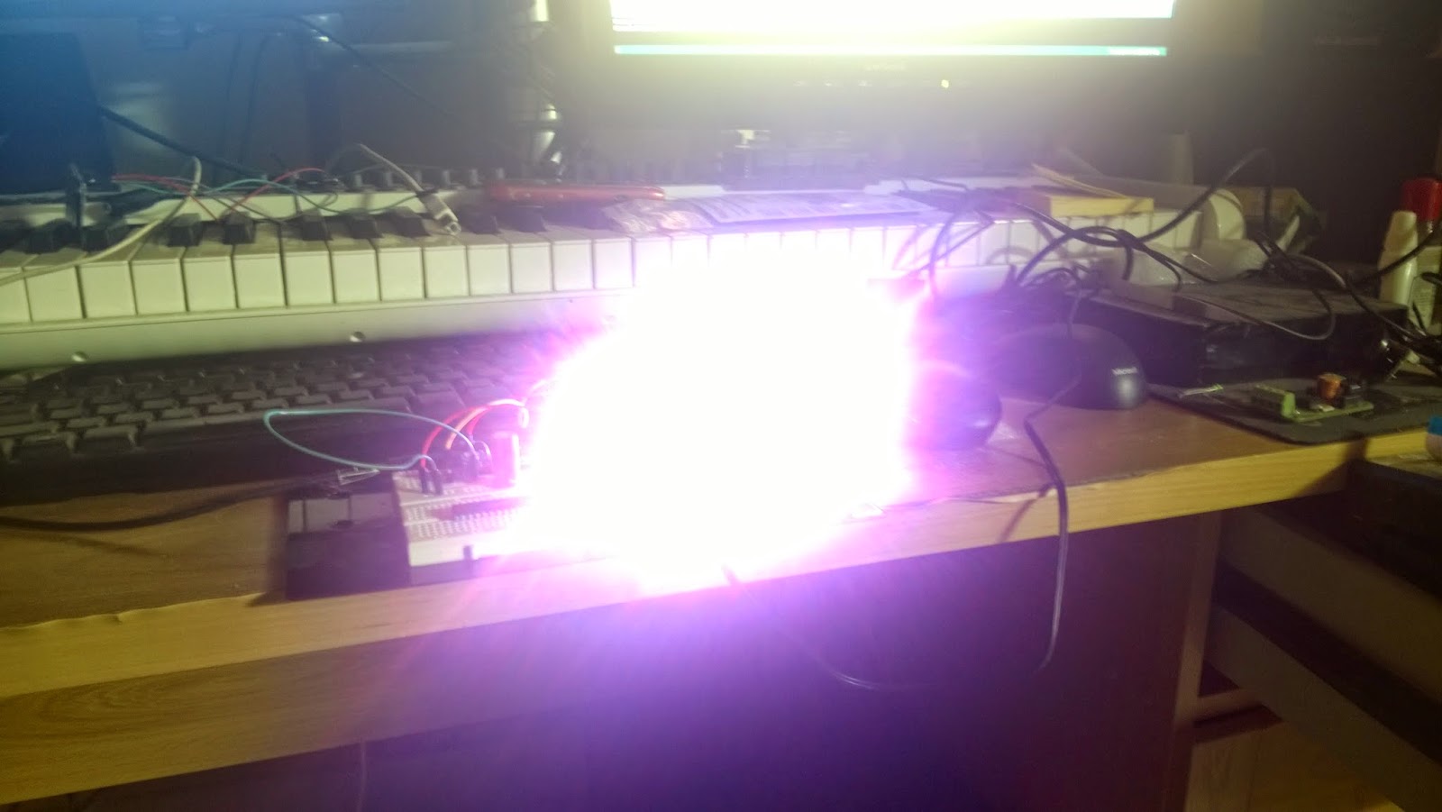
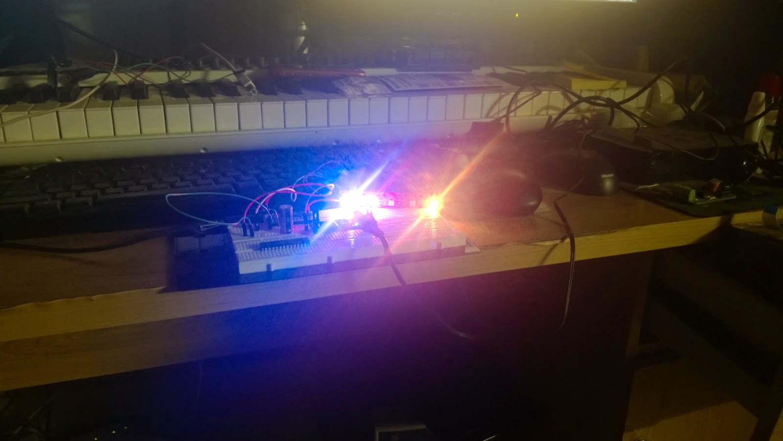
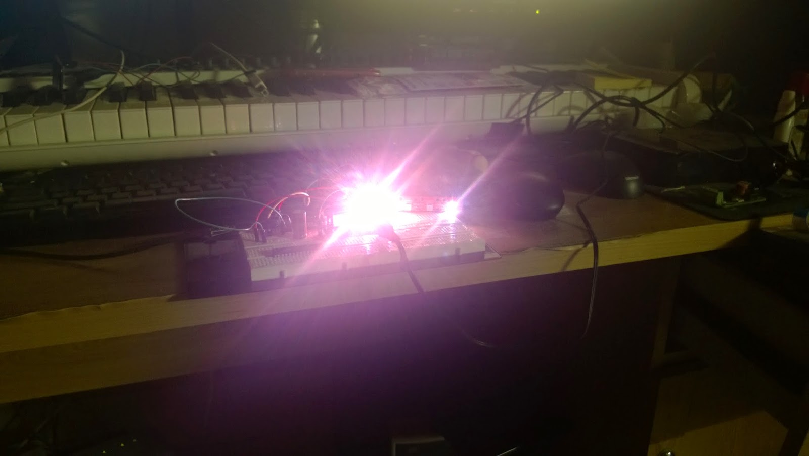
Some images of the setup and the LEDs in action. CAUTION: These LEDs are exceptionally bright. DO NOT LOOK directly into them. Use a diffused material to shield or a camera or perhaps some shades to look at them..


    A State of Trance on my desk :P

   Shot at a lower ISO and high shutter speed


On the Teensy i used the following code to read MIDI information and based on the channel turn ON/OFF the corresonding LED. The color for the LEDs is randomized. You will also have to create a duplicate MIDI track for the actual instrument and route the MIDI to the USB Audio Device. This way you can simultaeneously listen to the track and send MIDI to the Teensy.