Tuesday, March 25, 2014

The nRF24L01+ Nightmare


I got these cool RF tranciever breakout boards from eBay based on the nRF24L01+ chip from Nordic Semiconductors. You can find lots of info from the web on interfacing these with Arduino boards. More info on these chips can be found here. My main intent is to use the breakouts with  Teensy 3.x development boards using the RF24 library by maniacbug. A few adjustments are necessary to make the library compile with the Teensy e.g. removal of a printf based API. I have a Teensy 3.0 and a Teensy 3.1, one is to act as a transmitter [TX] and the other, a reciever [RX]. I did not care to use the available examples like the ping pong etc. Instead i wrote my own program to remotely blink an led using the value transmitted by the TX. Following are actual events that occured to get the whole thing running properly at max power and 1 Mbps datarate.

Day 1:

nRFs interfaced to both Teensy's. All connections double checked. Program the TX. Program the RX. Nothing happens. A webhunt ensues. Lots of people facing problems with interfacing Teensy to the nRFs but nothing relevant to mine. Have i purchased defective merchandise ? Time to print sh**. Time to use my Arduino UNO board, as the RF24 library worked without any problems with the printf API. Printed the device status which turned out to be OK. I let the arduino do the TX, still nothing happened. I pull the USB programming cable out of the RX Teensy and reset it. After 5 hours of starting all this, I am jack's flashing LED. The LED connected to the RX board started to blink. So now the Arduino does all the TX and the Teensy the RX. Call it a fu**in' day.

Day 2:

So now we know that if you leave the USB cable connected to the Teensy, the nRF does not work. Well, i found in RX mode that the nRF consumes 11.5 mA as its continuously checking for data. So i used a breadboard power supply sourced from a 12V 2.5A DC adapter. Now both RX and TX are powered from the breadboad powersupply. The TX is on a separate breadboard to which power lines have been connected from the RX BB. Same code as Day 1. Program both RX and TX. Unplug the USB cable. Power OFF, Power ON. Nothing happens.....

Day 3:

Interchange the roles of the breakouts and tested on Arduino without any problem. So there has to be only one problem - the breadboard. I removed the Teensy from the TX BB and placed it on the RX BB, which is much larger as shown below. Connections complete. programming done, USB cable out. Power OFF, Power ON........LED Flashing. So, it had something to do with the breadboard, i am guessing it had a short somewhere or was not of good quality - one of those spring types. Also the SPI bus operation at high frequency and breadboards are not a good match. The circuit does operate with a few glitches now and then, but much better that what it used to do before. If you connect the USB cable to the Teensy USB port in the middle of a successful operation the transmission screws up. This does not happen with an Arduino. That is some wierd bullshit. So, a lesson learnt -  Use good quality breadboards when messing with SPI peripherals. Infact it's best to design a small PCB with proper ground plane to accomodate SPI peripherals and reduce as much web-of-wires as possible. If you read this and have any info  that could be useful, feel free to leave it in the comments section.

The final setup. The L.H.S is the RX and R.H.S the TX. Highly recommended to avoid such a setup on a breadboard with the Teensy's and nRFs and all those wires.

Following is the code for the RX and TX Teensy's. RX is on a Teensy 3.1 and TX on a 3.0.

Sunday, March 16, 2014

FreeRTOS on Teensy 3.1

 
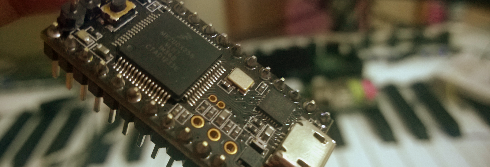
This post is about running FreeRTOS on a Teensy 3.1 board from PJRC. It is not a detailed in-depth coverage but will get you started. If you have not heard about this board you can find it here. Since my last post on making FreeRTOS run on the BeagleBoard, which was a nice learning experience, i've been porting FreeRTOS on anything i can get my hands on - a blender, television, chickens. You see, to port FreeRTOS on a chicken all you have to do is shove a compiled image up it's...never mind. Let's get started with this thing. First the pre-requisites

Pre-requisites:
- Teensy 3.1
- Arduino 1.0.5 with the support for Teensy installed.
- FreeRTOS source code
- Cortex M Series TRM (duh)
- Datasheet of the MK20DX256VLH7 (you probably will not open it)


FreeRTOS:
FreeRTOS can be downloaded from the website. The latest version 8.0.0 has ports for Cortex M devices  already. You can refer to that and it's accompanying demo example. As we are using the Teensy here some minor modifications are necessary. In the portable directory we need to look inside the GCC sub-directory as the arduino uses the gcc toolchain for code compilation. Within the GCC directory there will be three sub-folders - ARM_CM0, ARM_CM3, ARM_CM3_MPU, ARM_CM4F. I used the ARM_CM3 port for the Teensy as it was simple and did not create unnecessary link errors. Perhaps i will try with the MPU version later. Do not use the ARM_CM4/F port, in my opinion it is wierd, maybe just not for this board.
The directory structure
- Source: The FreeRTOS source code.
- Source/include: The header files
- Source/portable: Target dependent files. For the Cortex these will be in the ARM_CM3 sub-directory inside GCC within portable, jeez...


Procedure:
1. Make a duplicate copy of the Arduino folder as a back up in case you need to revert back the code.
2. Copy all the FreeRTOS C / headers / portable files into the /Arduino1.0.5/hardware/teensy/cores/teensy3.
3. Copy the memory manager of you choice, i chose heap_2.c, from FreeRTOS's MemMang directory to the directory in [2].
4. The Teensy 3.1 has a 256K flash but it uses the mk20dx128.c file as it's startup. This file needs some editing as mentioned below.

4.1. Include FreeRTOS.h and task.h
4.2. stick_default_isr needs to be commented out, we shall see why later in [4.5]
4.3. I defined vApplicationStackOverflowHook function in this file.
4.4. Comment out prototype declaration for svcall_isr, pendablesrvreq_isr and systic_isr. Yes, i will not be using CMSIS naming conventions.
4.5. Replace the functions mentioned in [4.4] with vPortSVCHandler, xPortPendSVHandler, xPortSysTickHandler respectively  in the gVectors array. 
4.6. In the ResetHandler function comment out the initialization of the Systick as we shall be doing that during FreeRTOS initialization.
5. To setup the heap, mk20dx256.ld linker script needs to be modified. Here add a new region .heap as shown below. "heapsection" is the name given in as the __attribute__ for the static heap. This will not be present in the original file and needs to be modified as:

static uint8_t ucHeap[ configTOTAL_HEAP_SIZE ]  __attribute__ ((section(".heapsection")));

6. I setup my FreeRTOSconfig.h as shown below

7. I then edited the main.cpp file to test the FreeRTOS functionality.


Well this should get FreeRTOS running, if you get any compiling / linking errors then i probably missed out something, but i am confident you can fix those yourself. FreeRTOS runs like a charm on this board only limited by it's memory capacity. Now there are problems with the rest of the Arduino code not being thread-safe and not designed to run under an OS. There is a discussion on the same on the Teensy forum right here - http://forum.pjrc.com/threads/540-ChibiOS-RTand-FreeRTOS-for-Teensy-3-0

I have a very busy schedule and it takes time to implement and write up all this stuff. I will be updating this post with new findings as i go forward with this like the maximum tasks that can be run, etc... 

Code:
https://github.com/circuitsenses/Teensy-3.1-FreeRTOS

Happy Coding... 
P.S - Notice that you never referred to the MK20DX256VLH7 datasheet :P