This post is all about running
FreeRTOS on a Beagleboard Rev C3 with the OMAP 3530 processor from TI. The intention of this post is to serve as a reference for porting operating systems over various
platforms and cover a few basics in the process. You might wonder - Why port
FreeRTOS on a Cortex A8 based hardware? Well, its fun and a great learning
process. I am assuming that the reader has at least intermediate knowledge of
ARM architecture. This basic port is functional at this stage but still needs considerable polishing.
Pre-requisites:
- Beagle Board Rev C3
- ARM DS-5 Suite (Evaluation)
- XLoader & U-Boot Sources
- FreeRTOS source code
- Arm-linux-gnueabi toolchain
- A SD card.
- Mkimage utility
- OMAP 3530 TRM
- ARM ARM
- Lots of patience
-12 gauge loaded shotgun.
FreeRTOS
FreeRTOS can be downloaded from
the
website. The latest version 7.5.2 has a port for Cortex A9 based device
already. You can refer to that and its accompanying demo example. As we are
using the BB here, these files cannot be used in the implementation but just as
a reference. I however, chose to use the FreeRTOS version that was pretty old
and released in 2010 to keep distractions away and that I could do things my
way. Once this is a success i shall proceed to do the same with the latest update of FreeRTOS
The directory structure
- Source: The FreeRTOS source code.
- Source/include: The header files
- Source/portable: Target dependent files. For the ARM
architecture these will be in the RVDS sub-directory of portable.
Approach
Before diving
into creating a project, compilation etc it is essential to outline the various
aspects the port might need and come up with basic software architecture and
files required.
You must be
aware of the features provided by FreeRTOS. These can be found
here. It has a
small footprint – which is enough for the friggin’ 256 MB of RAM on the BB. The
scheduler is pre-emptive (I chose to operate it in pre-emptive mode) hence
there will be a tick timer involved and a few other mainstream OS features. Hence
we need one hardware tick timer from the OMAP for the OS tick and a UART for
debug logs. There also has to be some kind of memory manger / allocation system.
This can be found in the MemMang sub-directory of portable - three memory
managers for the OS heap. It is also essential to know the memory mapping of
the BB and the OMAP3530. On the BB the RAM is mapped to address 0x80000000.
Refer OMAP TRM for memory mapped peripherals.
For any port
there will be a bunch of files that will be target / architecture dependent
(usually assembly) and a few C files that will be architecture independent.
These files do not need any modification and can be used as is. In case of
FreeRTOS the C files in the source directory can be used as is, so create your project folder and copy them in that,
including the headers in the include sub-directory.
As mentioned
earlier the files that will require porting will be the ones in the RVDS
sub-directory of portable. Now then, in my case I have used port.c and
portmacro.h from the ARM7_LPC21xx directory. The portASM.s file cannot be used directly
as it’s for the LPC processors from NXP. It needs modifications. Portmacro.inc
contains context save and restore macros. We also have to use the startup.s
file for the Beagleboard. Initially copy the two files mentioned above to your
directory. The startup file for Beagleboard can be found in the fireworks demo
application for the Beagleboard in DS-5. Copy this file to your workspace to be
changed later. Then copy heap_2.c to your project directory, this will be the
memory manager. Every demo project has a FreeRTOSConfig.h header file which contains OS options that can be enabled / disabled or modified e.g. the
pre-emption, timer tick rate, heap size etc. This file needs to be copied to
the project workspace.
The Beagleboard boot process
Here is a brief
summary of the BB boot process. The internal ROM code transfers the control to
XLoader. Internally a call to start_armboot
from start.S file for omap3 starts the minimal board initialization for u-boot
to run. On a BB the default boot device is the NAND flash which contains the
u-boot binary. To boot off the mmc card the USER button needs to be pressed
when releasing the board RESET button. At this point XLoader will load the mmc u-boot
image to the address 0x80008000 defined by the macro CFG_LOADADDR. After loading, control jumps straight to u-boot.
U-boot does its
necessary setup for clocks, plls, sdram initializations etc and prepares the board
to load linux. Now here lies the rub, we do not want to run linux, we want to
run FreeRTOS. We therefore have a few options – Create an OS image / bin file
that will be directly executed by XLoader or create an image that will be
loaded via u-boot. In the former case the final OS image will have to be named
u-boot.bin, (because that is the name the XLoader hunts for when booting from
mmc) which will be loaded at address 0x80008000. The latter case is not so
trivial, because in this case we will have to provide a bin file with a proper
u-boot header such that u-boot can understand and therefore load. This header
will be appended to the OS image by the mkimage utility as we shall see later. I
chose to load from u-boot, thereby letting u-boot initialize the entire board.
During boot, a
script file is also used to execute few commands. This script file is generated
from a boot.cmd (you can name it anything) file using the mkimage utility. This loads the image via the
source command in u-boot. It hunts the directory structure for the script image
and begins to load based on the information in the script. The details of which
will be discussed later. The XLoader and U-Boot sources that I used can be
found in the below GIT repositories.
Final checklist
- XLoader and U-Boot source.
- FreeRTOS sources and headers
(croutine.c, list.c, queue.c, tasks.c, include folder)
- FreeRTOS ports for ARM –
(port.c, portASM.S startup.S, portmacro.h, portmacro.inc, FreeRTOSConfig.h)
- FreeRTOS memory manager –
(heap_2.c)
Stage 1: Modifying U-boot to load FreeRTOS
Here we shall
see how we can load any OS or bare-metal application from u-boot without making
considerable changes to u-boot code.
After the
autoboot promt times-out u-boot will read the boot.scr file from the mmc. This
file was created using the boot.cmd file whose contents were as follows
fatload mmc 0 80000000 freertosimg
bootm 80000000
The first
command loads the OS image file which is in u-boot format to the RAM address
0x80000000. The second line calls the u-boot command bootm which starts execution from the specified address.
If we see the
implementation of the bootm command it ultimately makes a call to the function do_bootm_linux (\arch\arm\lib\bootm.c).
Here it prepares to load the linux image and finally transfer control to the
kernel from the boot_jump_linux
function. To avoid all this, one can comment out the original implementation of
do_bootm_linux and write a new
function with the same name which will call a new function – boot_jump_freertos. This function will
take a bootm_headers_t pointer
variable and a flag.
Prototype: static void
boot_jump_freertos(bootm_headers_t *images, int flag)
The
implementation is shown below. I chose not to create a new function but called
my function right at the beginning thereby skipping the other stuff.
The 0x40 has
been added such that the execution starts at an offset of 0x40 from the base of
RAM. The initial 0x40 bytes belong to the header. Weird stuff but its tolerable.
That is it. The u-boot modification has been done. The code can be built and
the final u-boot.bin and img files can be written to the mmc card. Make sure
the SD card is formatted according to the instructions given
here.
Stage 2: startup.S
When kernel_entry will be called from u-boot,
the control will be transferred to the startup.S file for the BB. This is the standard BB
startup file that initializes the cortex A8 MMU, caches and sets up the vector
table etc. At this point we must setup the stacks for each mode of the
processor, initialize the MMU before calling __main. We must have a specific mapping of the memory regions that
we will specify in the scatter file. For the BB, I chose to follow the below
structure

All regions are
1 MB in size. The APP CODE region is write-protected by setting the appropriate
AP bits in its translation table descriptor. Only first level translation has
been used that makes up for 4096 translation table entries governing 4096 1 MB regions
- simple. All other regions are RW. The entire stack region of 1 MB contains
four 256 kb regions for the stacks of respective modes. There is no User/System
stack, the reason for this is that FreeRTOS tasks run in System Mode and the
task stacks are allocated from the heap. Whenever a context switch happens the
SP is loaded with the address of the stack allocated in the heap. The scheduler
runs in SVC or Supervisor mode. At this stage let’s spare the vector table. All
we do is just set the VBAR register in CP15.
Stage 3: Main.c
After calling __main the code will do the necessary
library initialization, scatter loading and finally jump to a user defined main() function. To make things
modular, create a new file main.c and add some startup initialization into it.
Here is what I chose to do in main.c
- enable_caches();
- init_uart();
- init_int_controller();
- start_freeRTOS();
Enable caches after scatter loading.
Standard procedure.
Initialize the
UART. I chose to re-init the UART setup by u-boot by resetting it from the
System Control Register and re-configuring it for 115200, 8, n, 1. This code
can be put in a new file call it uart.c. Refer to the UART section in the OMAP
3530 TRM for detailed register description.
Initialize the
interrupt controller. Reset the interrupt controller. During code execution I
found an interrupt was being generated from one of the peripherals as a
consequence of u-boot actions, hence I chose to reset the interrupt controller
to clear any interrupts setup by u-boot. Place it in a new file called
interrupt_con.c
Transfer control to FreeRTOS scheduler
(vTaskStartScheduler())
Stage
4: Setting up the Timer Tick
Within the
scheduler initialization is a function called prvSetupTimerInterrupt that sets up the timer which will generate
the tick for the OS if it’s supposed to be preemptive. For this I used general
purpose timer 1 of the OMAP 3530 in auto reload mode. For the tick frequency I
decided to use a period of 10msec i.e. a timer interrupt triggered every 10ms.
Create a new file call it timer.c. Refer Timer section in OMAP 3530 TRM. A
rough overview of the steps is detailed below.
- Reset the timer
- Stop it, for no reason. Write a 0 to
TIMER1 TCLR register.
- Select the GP Timer 1 source clock
as the 32 KHz clock in the CM (PRCM Module)
- Write a 1 to the CM FCLKEN bit.
- Setup the timer TCRR and TLDR
registers with a count to generate a 10 ms tick. I figured a formula for that
headache - TCRR Count = TLDR Count = 0xFFFFFFFF – (Delay Time / 31.25usec) where
delay is the required delay #ftw. Essentially it looks like:
*GPTIMER1_TCRR = 0xFFFFFFFF - 0x140; // Initial value to start
incrementing
*GPTIMER1_TLDR = 0xFFFFFFFF - 0x140; // Reload value after overflow
- Clear all pending events for the
timer by writing to the TISR register.
- Enable the overflow event in the
TIER register.
- Clear the mask for the GP Timer 1
IRQ in the Interrupt controller. (Refer TRM)
- Set auto reload mode for the timer.
Write a value of 3 to TCLR register.
- Execute a system wide DSB intrinsic
(__dsb (15)) to synchronize.
The timer interrupt
hander is the function vPreemptiveTick
can be found in portasm.S file. The interrupt handler in the startup.S file now
needs to be modified as shown below. Basically we just check and verify that it
was an interrupt from timer 1 and branch off to the interrupt handler i.e. the
tick function. Make sure not to use BL instruction within the IRQ handler as
it will corrupt the LR of the IRQ mode and make you want to use that shot gun I
mentioned earlier. Note that I have not used nested interrupts to keep things
simple. (PS – I do not even have a debugger if things go wrong. #ftw)
After the interrupt
has been serviced it needs to clear the timer event and acknowledge the
interrupt so that subsequent interrupts can be processed. The code for this can
be inserted in the portRESTORE_CONTEXT macro at the end of the macro as shown
below.
Stage
5: vPortYieldProcessor
vPortYieldProcessor is used to manually
force a context switch. It is initiated by a SVC (formerly SWI) instruction
that switches the processor to SVC mode. The SVC exception handler needs to be
setup to call vPortYieldProcessor.
The below image shows the SVC handler, it also shows other exception handlers
that I setup for reporting errors. Since I do not have a debugger all the
errors were reported via the UART. For data aborts and prefetch aborts the
contents of DFSR and DFAR, IFSR were extracted from CP15 registers. You can
create a separate file called crash.c to implement the handlers for DABT and
PABT and another file called coputil.s for the CP15 driver.
Stage 6: Setup the heap
The memory manager
heap_2.c needs to be setup such that it utilizes the 1 MB section ARM_LIB_HEAP
defined in the scatter file. This can be done by placing the heap structure in
the above region using the place in section attribute as shown below
Stage
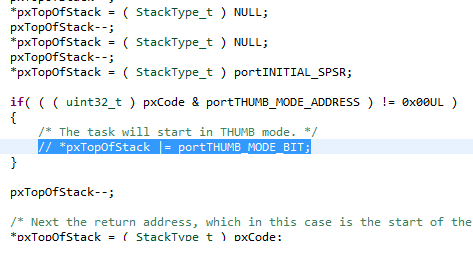
7: Setup everything in ARM mode
In the file port.c
there is a function pxPortInitialiseStack. Inside this FreeRTOS will setup the
stack to make it look like we returned from an IRQ handler. At the end of the
function after setting up the stack entry for the SPSR, it sets up the T bit
for the processor. I wanted my tasks and the whole OS to run in ARM mode. Hence
I commented out this section.
Stage 8: Configure FreeRTOSconfig.h
Well the screenshot
below is self explanatory. Set the tick value to 100. Heap size to 1MB. The
clock setting does not matter in this case or I don’t give a damn about it.
Stage 9: Build and Deploy
ARM-DS 5 will
generally build everything provided you set it up properly. I assume that you
know this. Setup the CPU type, apcs value, --unaligned-access for the C compiler,
scatter loading file, entry point etc.
The final output
will be a freertos.axf file in the debug directory (based on your settings)
that needs to be converted to a bin file by using the fromelf utility.
fromelf --binary
freertos.axf --output freertos.bin
The u-boot header
mentioned earlier can be applied as
mkimage -A arm -O
linux -T kernel -C none -a 0x80000000 -e 0x80000000 -n "Cortex A8
FreeRTOS" -d freertos.bin freertosimg
The freertosimg can
now be copied to the sdcard.
To create the
script file, first create a boot.cmd file with the contents
fatload mmc 0 80000000 freertosimg
bootm 80000000
Then execute mkimage as
mkimage –A arm –O linux –T kernel
–C none –a 0 –e 0 –n “Cortex A8 Image” –d boot.cmd boot.scr
boot.scr can now be copied to the
sdcard.
Insert the
sdcard into the board and boot from mmc. If all goes well you should see your
application running. In my case I just blinked the two user led’s on the board
using the flash task that comes with the demo. Here are a few more screenshots
of the process.
Debugging !!!
Running !!!
A note – this
was not meant to be a precise description but just a reference. You can use
this to try deploying your FreeRTOS on any other board. This is a long write up
& I could have missed something. If you get stuck trying this or have any
questions please post them in the comments below. I will keep updating this
post with newer items and “fixes”.
Thanks for watching.