Here is a quick summary of getting Linux to run on Digilents' Zybo FPGA board.
Prerequisites:
-1. Get the Zybo board from Digilent.
0. Get the latest Xilinx Vivado Suite and Xilinx SDK.
1. Get Linux-Digilent-Dev master-next branch from here.
2. Get U-Boot-Digilent-Dev master-next branch from here.
3. Get the zybo base system design from the Digilent webpage here.
4. Get Teraterm/PuTTY.
5. Get U-Boot-Tools and GParted.
6. 5V 1A+ D.C adapter
# export ARCH=arm CROSS_COMPILE=arm-xilinx-linux-gnueabi-
# source/Vivado/2016.2/settings64.sh
Preferably add the above to PATH in .bashrc

Compile u-boot by executing -
# make zynq_zybo_config
# make
Navigate to the kernel source directory and execute the following commands -
# make xilinx_zynq_defconfig
# make UIMAGE_LOADADDR=0x00008000 uImage
Once the build process is complete you will find the uImage file at /arch/arm/boot folder.

After making the changes execute [from the kernel root] -
# make zynq-zybo.dts
# sudo mount -o loop xillinux-1.3.img -o offset=$((512*32130)) /media/xiltemp
[in case you do not have a media folder just do it in /mnt/]
Now insert a blank sd-card preferably 8GB and make two partitions on it using GParted
1. BOOT [1 GB] [FAT32]
2. ROOTFS [Remaining Space] [EXT4]
Assuming that the sdcard is /dev/sdb2, mount it in a temporary location -
# sudo mount /dev/sdb2 /media/sdroot
Assuming your present working directory is /media/xiltemp then -
# sudo rsync -a ./ /media/sdroot
Similarly you can mount sdb1 and copy over the two files we generated earlier
- uImage
- devicetree.dtb
Eject the sdcard.
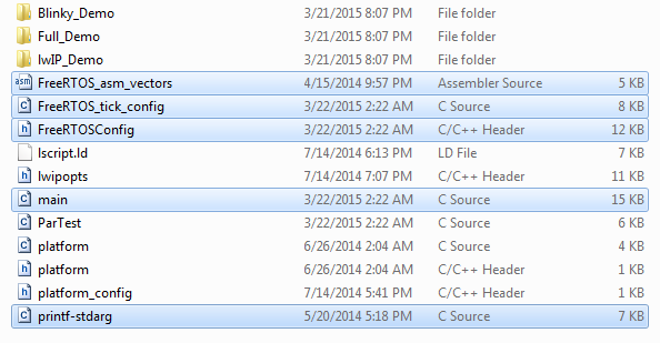
BOOT.bin
uImage
devicetree.dtb

auto eth0
iface lo inet loopback
iface eth0 inet dhcp
Reboot !
I've used Vivado 2016.2 on Ubuntu 14.04 LTS 64-Bit in Virtualbox for the kernel and u-boot build process and Vivado 2015.2 on Windows 10 for the base system, FSBL and FPGA bitfile build.
Prerequisites:
-1. Get the Zybo board from Digilent.
0. Get the latest Xilinx Vivado Suite and Xilinx SDK.
1. Get Linux-Digilent-Dev master-next branch from here.
2. Get U-Boot-Digilent-Dev master-next branch from here.
3. Get the zybo base system design from the Digilent webpage here.
4. Get Teraterm/PuTTY.
5. Get U-Boot-Tools and GParted.
6. 5V 1A+ D.C adapter
1. Open a new terminal and run -
# source
Preferably add the above to PATH in .bashrc
2. Compile U-Boot -
I have not used the ramdisk but a root file system based on Xillinux. Therefore the zynq_zybo.h file in /include/configs folder needs to be changed as shown below.

Compile u-boot by executing -
# make zynq_zybo_config
# make
Once the build process is complete there will be a file named u-boot in the root directory. Rename it to u-boot.elf. This file will later be used to generate BOOT.bin in the Xilinx SDK.
3. Compile the Linux Kernel -
Navigate to the kernel source directory and execute the following commands -
# make xilinx_zynq_defconfig
# make UIMAGE_LOADADDR=0x00008000 uImage
Once the build process is complete you will find the uImage file at /arch/arm/boot folder.
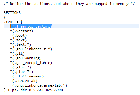
4. Compile the Device Tree -
Before compiling the device tree and generating the device tree-blob a few changes are necessary to be done in the file /arch/arm/boot/dts/zynq-zybo.dts as shown below. Then changes are majorly to edit the clocks and the bootargs as shown below

After making the changes execute [from the kernel root] -
# make zynq-zybo.dts
This will generate the device tree blob zynq-zybo.dtb at /arch/arm/boot/dts/. Rename the file to devicetree.dtb.
5. Prepare the SD Card -
5. Prepare the SD Card -
The rootfs that i have used is based on the Xillinux distribution. A link to download the rootfs can be found on this page or at this direct link.
Once you've downloaded the rootfs, extract it into a folder. A file named xillinux-1.3.img will be extracted into your directory. Mount the img file into a temporary location by executing the following command -
# sudo mount -o loop xillinux-1.3.img -o offset=$((512*32130)) /media/xiltemp
[in case you do not have a media folder just do it in /mnt/
Now insert a blank sd-card preferably 8GB and make two partitions on it using GParted
1. BOOT [1 GB] [FAT32]
2. ROOTFS [Remaining Space] [EXT4]
Assuming that the sdcard is /dev/sdb2, mount it in a temporary location -
# sudo mount /dev/sdb2 /media/sdroot
Now it's time to copy the img file contents at /media/xiltemp to the sdcard partition at /media/sdroot. the best way to do so is using the rsync command as shown.
Assuming your present working directory is /media/xiltemp then -
# sudo rsync -a ./ /media/sdroot
Similarly you can mount sdb1 and copy over the two files we generated earlier
- uImage
- devicetree.dtb
Eject the sdcard.
The next step is to build the base system and the FSBL. Depending on your situation you can proceed in Linux with identical procedure. Since i was using Virtualbox and Vivado generate bitstream takes ages, i chose to run the next steps in my Windows machine. Therefore using a shared folder i transferred u-boot.elf to Windows.
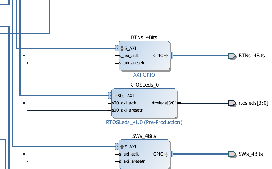
6. Build the Base System and FSBL -
Open the base system project file in Vivado. Upgrade all IPs if you get warning and hit the generate bitstream button. Once the process completes the system_wrapper.bit file will be found at -
\zybo_base_system\zybo_base_system\source\vivado\SDK\hw_platform
Now Launch the SDK and export the bit-stream. In the Xilinx SDK, create a new application project and select Zynq FSBL from the templates.
Now we need to modify the fsbl_hooks.c file and set the mac
address. Locate the ZYBO specific fsbl_hooks.c file in the
zybo_base_system/source/vivado/SDK/fsbl folder and replace the one that
was generated in the SDK fsbl project. Once you have replaced the
fsbl_hooks clean and build the project. This will generate the fsbl.elf
used to create the BOOT.bin in the next step.
Select create Zynq Boot image under the Xilinx Tools tab. We need to
add, in order, the fsbl.elf, system_wrapper.bit, and the u-boot.elf in
order to create the BOOT.bin. The fsbl can be found in the
zybo_base_system/source/vivado/hw/zybo_bsd/zybo_bsd.sdk/fsbl/debug
folder. Next specify the output path where you want the BOOT.bin to be
generated.
Copy BOOT.bin to the BOOT partition of the sd-card. The BOOT partition should now contain the following files -
BOOT.bin
uImage
devicetree.dtb
7. Boot Zybo
Insert the SD-Card into the Zybo, select JP5 jumper to SD and J15 to wall. Connect the USB to a serial terminal like Teraterm or putty and power ON the board. If everything went well the logs should get displayed on the screen and you will finally get a command prompt.

Additional Observations:
- Digilent recommends use of a 2.5A 5V D.C power adapter when using the board with Linux. However, i found out that a 1A adapter was sufficient to boot the board.
- GParted sucks. Use fdisk to partition the sdcard. A better solution is to use this script. The mkcard utility that you can modify as per your requirement.
- Once you successfully boot linux. You can download the same kernel from Digilents' linux GIT repository onto the sdcard filesystem. You might have to enable the ethernet. To do so open /etc/network/interfaces in nano and add modify it as below - [will vary based on your N/W configuration]
auto eth0
iface lo inet loopback
iface eth0 inet dhcp
Reboot !
- You can now get the kernel and build it on the Zybo. The kernel build takes approximately 45 minutes. But most importantly - Install vim !!!


