Friday, July 22, 2016

ARM FastModels - Part 1 - The SoC

The ARM FastModels series of posts will be focusing on building a simple SoC from scratch, bringing up FreeRTOS on the SoC, creating a custom IP using the native language LISA and porting of the SMSC91C111 Ethernet controller driver on the virtual platform. The links to each of the below topics will be enabled once the post is ready for hosting.

  • 1. The SoC hardware architecture.
  • 2. Bringing up Free RTOS on the SoC.
  • 3. Adding a custom peripheral IP.
  • 4. Porting the Network Controller driver.

I have been playing around with FastModels for quiet some time and it is a fascinating tool to design and build your own SoC Virtual Prototype from scratch and learn the process of interfacing various IPs to the SoC. More information on FastModels can be found here. It is available for a 30 day trial for a processor of your choice. I chose the Cortex-A5 MPCore processor and therefore the SoC will be designed around it. Using the tool-chain is pretty basic and can be almost easily followed through using the available user guides. Remember i said 'almost'. Most advanced features and IPs are not well documented or are proprietary and it could give you a concussion if you try to interface them.

If you are running on Windows then you need a full version of Visual Studio 2013 to compile the simulation ISIM executable. On Linux you can use the freely available gcc 4.8 compiler. I am using FastModels 10 on a Windows machine with a VS2013 60-day trial.

For my SoC code-named RAVEN i decided to go for a simple hardware architecture that consisted of a Cortex A5 Quad Core processor clocked at 500 MHz, PL011 UART IP, 1GB of RAM, SMSC91C111 Ethernet controller. This being a simulation, not all core features are available. To check out the features that are available for the Cortex A5MPCore model view the DUI0834H Fast Models reference manual section 3.2.15.

The Cortex-A5 model can provide full functional simulation of the ARM v7 architecture and comes bundled with the SCU, GIC, Private timer and WDT per core, one Global Timer and an Advanced Coherency Port. You can refer the A5 MPCore reference manual here.

The FastModels design environment is a code based and block design based IDE akin to a Visual Programming IDE where you can drag and drop various IPs and connect them. If you have used tools like Xilinx Vivado or Multisim bob's your uncle. The scripting language is called LISA and is similar to C++. 


The final SoC is shown above. Starting from the left -

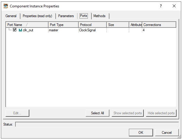
XTAL: The Master Clock IP. a clock signal of 1 Hz is available at the clk_out port of this IP. The clk_out master port follows the ClockSignal protocol and can only be connected to another IP that has a port e.g. clk_in declared as a slave port with ClockSignal protocol. A list of available protocols is in the reference manual. To view the IP properties, right click the IP block and select Object Properties which brings up the following dialog box.


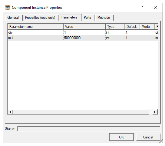
CORE_CLK: This is a Clock Divider IP. This IP can either multiply or divide the clock frequency that is input at its clk_in terminal. The new clock signal comes out of the clk_out signal. This IP has been used to provide the clock frequency for the Cortex-A5. As shown below the mul parameter of this IP is 500000000. Since the input to the divider is 1 Hz it is multiplied by 500000000 to give a frequency of 500 MHz.This output is connected to the clk_in port of the processor.


PERIPHERAL_CLK: This is again a Clock Divider with the mul parameter set to 166666666 i.e. 166.66 MHz. FastModels provide a functionally accurate simulation of the system and not a timing accurate hence these clock values seldom do not influence functional verification. However, according to the datasheet the peripheral clock must be an integral multiple [N] of the core clock period with the multiple being greater than or equal to 2. Given a 500 MHz clock with 2ns period selecting N = 3 gives a 3:1 ratio and the peripheral clock period as 6ns hence 166.66 MHz.

UART_CLK and ETHERNET_CLK: The clock dividers for the UART and ETHERNET IPs clocked at 15MHz and 25 MHz respectively.

BUSDECODER0: The bus decoder IP is responsible of routing the bus transactions to the respective slave devices on the bus.The transactions on the PVBus are similar to AXI transactions. As shown, this IP is connected to the pvbus_m port of the processor which is one of the MASTER AXI ports. Each of the slave interfaces on the pvbus_m_range master port must be configured with a base address and size of the slave peripheral which must be 4KB aligned. This forms the memory map for the peripherals as shown below.


Now then, i figured that it is just impossible to type everything in here. The best thing would be to demonstrate the entire design process. Here is the video of the SoC design in action !!


After the build is successful a isim executable will be created in a release/debug directory inside the project folder. This executable needs to be imported into DS-5 to run the software and for simulations.


Wednesday, July 6, 2016

Digilent Zybo - Linux Bringup 2016

Here is a quick summary of getting Linux to run on Digilents' Zybo FPGA board.

I've used Vivado 2016.2  on Ubuntu 14.04 LTS 64-Bit in Virtualbox for the kernel and u-boot build process and Vivado 2015.2 on Windows 10 for the base system, FSBL and FPGA bitfile build.

Prerequisites:
-1. Get the Zybo board from Digilent.
0. Get the latest Xilinx Vivado Suite and Xilinx SDK.
1. Get Linux-Digilent-Dev master-next branch from here.
2. Get U-Boot-Digilent-Dev master-next branch from here.
3. Get the zybo base system design from the Digilent webpage here.
4. Get Teraterm/PuTTY.
5. Get U-Boot-Tools and GParted.
6. 5V 1A+ D.C adapter

1. Open a new terminal and run -

# export ARCH=arm CROSS_COMPILE=arm-xilinx-linux-gnueabi-
# source /Vivado/2016.2/settings64.sh

Preferably add the above to PATH in .bashrc

2. Compile U-Boot -

I have not used the ramdisk but a root file system based on Xillinux. Therefore the zynq_zybo.h file in /include/configs folder needs to be changed as shown below.


Compile u-boot by executing -
# make zynq_zybo_config
# make

Once the build process is complete there will be a file named u-boot in the root directory. Rename it to u-boot.elf. This file will later be used to generate BOOT.bin in the Xilinx SDK.

3. Compile the Linux Kernel -

Navigate to the kernel source directory and execute the following commands -
# make xilinx_zynq_defconfig
# make UIMAGE_LOADADDR=0x00008000 uImage

Once the build process is complete you will find the uImage file at /arch/arm/boot folder.

4. Compile the Device Tree -

Before compiling the device tree and generating the device tree-blob a few changes are necessary to be done in the file /arch/arm/boot/dts/zynq-zybo.dts as shown below. Then changes are majorly to edit the clocks and the bootargs as shown below


After making the changes execute [from the kernel root] -
 # make zynq-zybo.dts

This will generate the device tree blob zynq-zybo.dtb at /arch/arm/boot/dts/. Rename the file to devicetree.dtb.


5. Prepare the SD Card -


The rootfs that i have used is based on the Xillinux distribution. A link to download the rootfs can be found on this page or at this direct link.

Once you've downloaded the rootfs, extract it into a folder. A file named xillinux-1.3.img will be extracted into your directory. Mount the img file into a temporary location by executing the following command -

# sudo mount -o loop xillinux-1.3.img -o offset=$((512*32130)) /media/xiltemp
[in case you do not have a media folder just do it in /mnt/]

Now insert a blank sd-card preferably 8GB and make two partitions on it using GParted
1. BOOT        [1 GB] [FAT32]
2. ROOTFS   [Remaining Space] [EXT4]

Assuming that the sdcard is /dev/sdb2, mount it in a temporary location -

# sudo mount /dev/sdb2 /media/sdroot


Now it's time to copy the img file contents at /media/xiltemp to the sdcard partition at /media/sdroot. the best way to do so is using the rsync command as shown.

Assuming your present working directory is  /media/xiltemp then -

# sudo rsync -a ./ /media/sdroot

Similarly you can mount sdb1 and copy over the two files we generated earlier

- uImage
- devicetree.dtb

Eject the sdcard.


The next step is to build the base system and the FSBL. Depending on your situation you can proceed in Linux with identical procedure. Since i was using Virtualbox and Vivado generate bitstream takes ages, i chose to run the next steps in my Windows machine. Therefore using a shared folder i transferred u-boot.elf to Windows.

6. Build the Base System and FSBL -

Open the base system project file in Vivado. Upgrade all IPs if you get warning and hit the generate bitstream button. Once the process completes the system_wrapper.bit file will be found at -
\zybo_base_system\zybo_base_system\source\vivado\SDK\hw_platform

Now Launch the SDK and export the bit-stream. In the Xilinx SDK, create a new application project and select Zynq FSBL from the templates.

Now we need to modify the fsbl_hooks.c file and set the mac address. Locate the ZYBO specific fsbl_hooks.c file in the zybo_base_system/source/vivado/SDK/fsbl folder and replace the one that was generated in the SDK fsbl project. Once you have replaced the fsbl_hooks clean and build the project. This will generate the fsbl.elf used to create the BOOT.bin in the next step.

Select create Zynq Boot image under the Xilinx Tools tab. We need to add, in order, the fsbl.elf, system_wrapper.bit, and the u-boot.elf in order to create the BOOT.bin. The fsbl can be found in the zybo_base_system/source/vivado/hw/zybo_bsd/zybo_bsd.sdk/fsbl/debug folder. Next specify the output path where you want the BOOT.bin to be generated.

Copy BOOT.bin to the BOOT partition of the sd-card. The BOOT partition should now contain the following files -

BOOT.bin
uImage
devicetree.dtb

7. Boot Zybo

Insert the SD-Card into the Zybo, select JP5 jumper to SD and J15 to wall. Connect the USB to a serial terminal like Teraterm or putty and power ON the board. If everything went well the logs should get displayed on the screen and you will finally get a command prompt.


Additional Observations:

- Digilent recommends use of a 2.5A 5V D.C power adapter when using the board with Linux. However, i found out that a 1A adapter was sufficient to boot the board.

- GParted sucks. Use fdisk to partition the sdcard. A better solution is to use this script. The mkcard utility that you can modify as per your requirement.

- Once you successfully boot linux. You can download the same kernel from Digilents' linux GIT repository onto the sdcard filesystem. You might have to enable the ethernet. To do so open /etc/network/interfaces in nano and add modify it as below - [will vary based on your N/W configuration]

auto eth0
iface lo inet loopback
iface eth0 inet dhcp 

Reboot !

- You can now get the kernel and build it on the Zybo. The kernel build takes approximately 45 minutes. But most importantly - Install vim !!!


Monday, April 4, 2016

Vibration Robot - Iteration 1 - Chaos

I was always fascinated with the Kilobots developed by Harvard and their amazing capabilities when operated in massive swarms of self-organizing robots. I therefore decided to build my own prototype using modules easily available locally. This was not going to be a Kilobot clone but something different based on the same principle. So recently i managed to wrangle up a few breakout boards to make a vibration robot as shown below. The modules used are as follows

Main board - Arduino Lilypad (ATMega328) from Sparkfun. The reason i chose this was due to the large number of I/O and because the PCB is circular. 50 mm diameter, 17 mm more than that of the Kilobot, which is around 33mm.

Communications - Adafruit Bluetooh EZ Serial link. This board snugly fit on top of the Lilypads serial connector. The main board could now be programmed wirelessly over the BT Serial link.

Motor Driver - A Spakrfun TB6612FNG 1A Dual H-Bridge based motor driver for the vibration motors.

Power Source - A 400mAh Li-Ion battery similar to this. (External charger)


The orange colored housing for the motors is designed in my favorite CAD tool and 3D printed on me printer. The position of the holes  for mounting the screws was calculated from the board files supplied by Sparkfun. The motors were glued in their sockets. The entire assembly was held together using M3 screws through the Lilypad holes.


The block diagram of the system is shown below. The ATMega328 operates off the 3.7 V Li-Ion battery, which also powers the BT serial. The motor driver is powered from the 3.3V regulator on the BT serial board and draws maximum 2.2 mA of supply current, which is within spec of the regulator on the BT serial board as it can source maximum 100 mA. The driving voltage for the motors comes directly from the battery. Other control and PWM signals are connected to the arduino PWM and digital I/O pins.


And the end result after all that was - Chaos - as you can see in the video below. The robot is controlled via a windows phone application that i wrote which connected over BT serial to the bot. A single 4-Byte (integer) command was sent to the bot comprising of :

Byte 0 - PWM value for motor A (0 - 255)
Byte 1 - PWM value for motor B (0 - 255)
Byte 2 - Control signals for motors: Bit 1 - Motor A CCW, Bit 2 - Motor B CCW, Bit 3 - STANDBY/STOP
Byte 3 - Reserved.


The objective was to send varying PWM values to the motors to observe a linear motion along a straight line and characterize the 2DOF aspects of the system. Not shown in the video is my phone through which i am controlling the robot by varying the PWM to the motors.


Further iterations will include several improvements over shortcomings in the current design - thinner wires, smaller or custom boards etc. Thanks for watching...


Saturday, February 13, 2016

The Collatz Conjecture - Part 1


The Collatz Conjecture can be summarized as follows - Take any positive integer n. If n is even, divide it by 2 to get n / 2. If n is odd, multiply it by 3 and add 1 to obtain 3n + 1. Repeat the process indefinitely. The conjecture is that no matter what number you start with, you will always eventually reach 1. The property has also been called oneness - Wikipedia

So, for starters, i decided to write a program that will compute the Collatz sequence for a 64 bit number i.e. from 0 to 18,446,744,073,709,551,615 which equals 264 − 1. After reaching the end of the cycle for a given number the program prints out the number N and the length of the cycle S. However, it does not print every cycle length, it only prints the next cycle that is greater than the previously computed cycle length.


The above code was compiled using gcc with full optimization. The executable was run on a 3.0 GHz Core i7 Quad with 8 GB RAM. The process priority was changed to SCHED_RR using the chrt command. It took the machine two weeks to generate the output shown below. The largest cycle sequence we were able to compute was 1428 for the 13 digit number shown. In the next part of this article i shall be posting details about running the same code on my NVidia GPU using CUDA along with some insane optimizations.


Oh, and there is also a short-film on the Collatz Conjecture...


Friday, February 12, 2016

Quadcopter Chronicles - I

So, i've decided to build my own drone from scratch. Here is a picture of the work in progress. The orange PLA chassis was printed on my 3D printer. It is going to be similar to the Crazyflie with a few modifications. So, why not buy the Crazyflie ? well, no fun in that...

So this is the X configuration. The slits have been cut into the motor housing to account for the error in the print caused by the 3D printer. I've observed with my printer that, if i give the hole diameter as 7.03 mm it always turns out to be less by around 0.2-0.1 mm, which is the error. When this happens the motors do not pass through the hole and i have to sit and file it which results in inconsistencies in the 4 holes.

By giving the same value of 7.03 mm is the diameter of the motor and a slit the motors can be accommodated in a tight fit by wedging the slit to allow the motors to pass though, removing the wedge causes the structure to wrap tightly around the motor due to it's elastic nature. 

Also there is something weird in the image below. If you figure it out leave a comment.


The body was designed in SolidWorks as shown below and weighs 9 grams. Yep, that is a lot of green, almost a relation fest, but i am learning to clean that up. Most of it is the symmetry relation due to mirroring the entities.


The motors and props are similar to the one used in the Crazyflie. The next task is to design the control system electronics.


If you would like to download the 3D STL model visit my Thingiverse link below:
http://www.thingiverse.com/thing:1336837

Licensed under Creative Commons